This is an old revision of the document!
Sonar
More specifically, passive SONAR.
This page is half presentation, half semi-coherent conversation with myself as I work through the problem of passive sonar, going from theory to implementation.
Operational Theory
Sensor Setup
Let's suppose we have a pair of audio transducers aka microphones. They are setup as below (m1 for microphone 1). Let's call the distance they are apart ds.

Perpendicular to Source
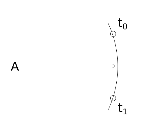
If this pair of microphones are perpendicular at their midpoint to a sound source (`A`), they will both hear/observe the sound source at the same moment. That is to say, if we noted the time when each microphone heard `A`, the difference in time would be `0`.
The curve represents the leading edge of the pressure wave (sound wave) emitted by sound source A. t0 represents the time in which the first microphone hears the sound and t1 represents the time when the second microphone hears the sound. If t1 - t0 = 0, the line formed between the sound source and the midpoint must be perpendicular to the line formed by the two microphones.
Colinear with Source
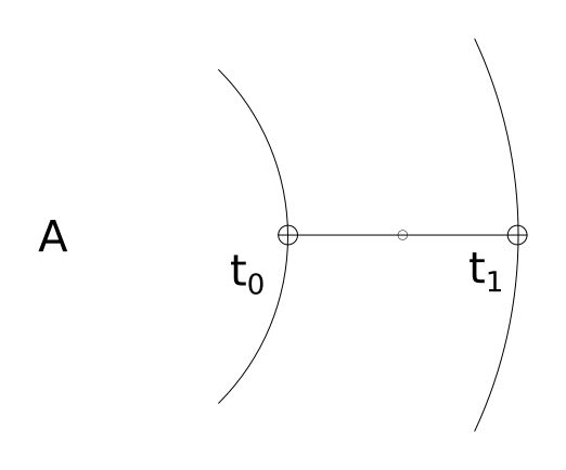
Suppose the pair of microphones have their midpoint (as well as themselves) colinear with sound source `A` as in the diagram below. The distance between the two microphones is known. That distance we have previously defined as ds. But this distance could also be determined by multiplying the time difference by the speed of sound1).
The key takeaway is that the time difference observed by the microphones gives the distance the sound wave traveled between the first microphone and the second microphone.
distance traveled by the wave between microphones = ( t1 - t0 ) * Ss
Thus if the distance traveled by the sound wave between m1 and m2 is 0, that means the sound source is perpendicular (at 90°) to the midpoint of the microphones
and
if the distance traveled by the sound wave between m1 and m2 is equal to ds, the distance of the microphones themselves, we know the sound source is colinear (at 0°) to microphones and their midpoint.
Somewhere between Colinear and Perpendicular
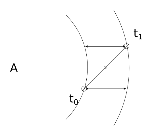
Because the distance the wave travels clearly varies relative to its angle from the midpoint, we know there must be some calculation to determine this angle.
Again, the distance the wave travels between m1 and m2 is determined by the time difference in observation. This distance is represented on the below diagram via the two lines with arrows.
Forming a Right Triangle
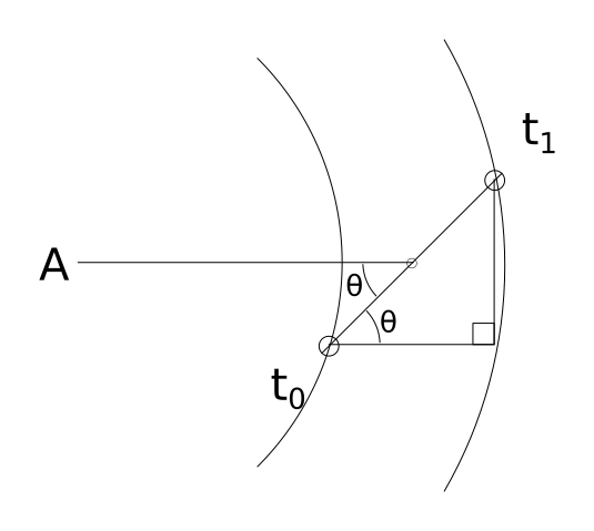
We can use this information to draw a triangle. The hypotenuse of the triangle is ds, the known distance between our microphones. The bottom leg is the distance determined via (t1 - t0)*Ss. Because the bottom leg of our triangle is parallel to the line going from the micropone midpoint to the sound source, the bottom left angle denoted by θ must be the same angle that is formed between the line connecting the microphones and the line connecting the midpoint to the sound source. See the below diagram.
θ can be determine with a little trigonometry. Since cos(θ) = adjacent/hypotenuse, we know that θ = arccos(adjacent/hypotenuse).
θ = arccos( [ (t1 - t0)*Ss ] / ds )
A line that passes through the microphone midpoint, at an angle of θ must, at some point, pass through the sound source.
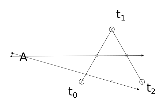
Triangulating
If a third microphone is added, we can repeat this whole process one more time with a different pair of microphones giving a second line pointing to the sound source. The point where these lines intersect is the location of the sound source. See below diagram.
Implementation
How does one turn the theory above into a working implementation?
Hardware
3x USB microphones mounted in an equilateral triangle configuration, connected to a computer (such as a raspberry pi) for signal processing.
Software
The software must monitor the signal from each microphone continually in 3μs rolling windows to attain 1mm resolution. This is not 1mm of accuracy to the source, but 1mm of accuracy for determining the distance the sound wave travels between the two microphones.
3μs gets 1mm resolution. The greater the distance the microphones are mounted apart, the greater resolution one can obtain. If the sensors are mounted 300mm apart, that means about 0.6 degrees of radial resolution.
At 3μs and sensors mounted 300mm apart, the sonar system can produce an angles from 0-180 in 0.6 degree increments.
A Fourier Transform is performed on each signal to isolate sounds and help connect each signal uniquely. The Fourier transforms allows signals below a certain amplitude to be ignored as well.
A simplified algorithm may work–one that only uses an amplitude threshold.
The math is pretty easy. Assuming we are using signed doubles, just take the average of the absolute value of each sample within the rolling sample window.
Taking Hardware Limitations into Consideration
Pretty standard sample rate is 44100hz. (44100hz)^-1 is 22.7μs. If we keep a sensor distance of 300mm, we can, at best detect distance in 9.9mm chunks. 9.9mm / 300mm * 180° = 5.9°.
So we would have an arc resolution of 5.9°. Call it 6°. That's not great, but for a screwing around project that only costs about $30 worth of hardware it may be good enough.
More Math
Once we have determined theta for two pairs of microphones, we need to find where the lines intersect.
Let x1,y1 be the first midpoint and x2,y2 be the second midpoint.
Assume the microphones are in an equilateral triangle configuration, the triangle's center of area is the origin point (0,0).
The top most microphone is on the y-axis.
The sound source is located at (xs,ys).
b1 is the y-intercept for the first line. b2 is the y-intercept for the second line.
tan(θ) will give the slope of a line, relative to the x-axis. However, when θ is determined, it is relative to the line formed by a pair of microphones. Thus, depending on which pair we are dealing with, θ must be adjusted.
If it is the bottom pair of microphones, no adjustment is needed.
If it is the left and top pair, use θ + 60.
If it is the top and right pair, use θ - 60.
Assume from here forward, θ? means an appropriately adjusted θ.
To determine b1:
b1 = y1 - tan(θ1) * x1
Repeat to determine b1.
Determine x1:
xs = ( b2 - b1 ) / ( tan(θ1) - tan(θ2) )
ys can be determined by substituting xs back into either of the previous equations.
ys = tan(θ1) * xs + b1
Code
Some very rough, very ugly, probably non-functional code.
This assumes a lot. But is based on everything written above this.
Will test and update once I get some hardware. Once I verify the code works (or rather, once I test it and fix all the bugs I find) I'll restructure the code out into more manageable functions.
- sonartest.c
/* Compile: gcc -Wall -std=gnu11 -lportaudio -lm sonartest.c -o sonartest */
#include <stdio.h>
#include <stdlib.h>
#include <stdint.h>
#include <time.h>
#include <math.h>
#include <portaudio.h>

#define MACH 343 // speed of sound in m/s
#define ds 0.3 // distance between sensors in m (should be in equilateral triangle shape)
#define ns_to_s(x) (x / 1000000000) // convert nanoseconds to seconds
#define pi 3.14159265358979323 // ... pi. Like the constant, y'know?


typedef struct {
	double x;
	double y;
} coord;

/* relative positions of sensors */
#define TOP 0
#define LEFT 1
#define RIGHT 2

#define TOPLEFT 0
#define LEFTRIGHT 1
#define RIGHTTOP 2

/* actual positions of sensors *midpoints* in meters from origin point*/


void initaudiohardware (void)
{
	/* init portaudio */
	PaError err;
	if ( (err = Pa_Initialize()) )
	{
		printf ( "Failed to init: %s\n", Pa_GetErrorText ( err ) );
		exit ( -1 );
	}

	/* uh.. sure */
	atexit((void (*)(void))Pa_Terminate);

	if ( 0 )
	{
	/* Figure out input devices we have */
	PaDeviceIndex dev;
	const PaDeviceInfo *dev_info;
	for ( dev = 0; dev < Pa_GetDeviceCount(); dev++ )
	{
		dev_info = Pa_GetDeviceInfo ( dev );
		printf (
			"Index: %d\n"
			"Name: %s\n"
			"Input Channels: %d\n"
			"Sample Rate: %f\n"
			"Default Low Input Latency: %f\n"
			"\n",
			dev, dev_info->name,
			dev_info->maxInputChannels,
			dev_info->defaultSampleRate,
			dev_info->defaultLowInputLatency );
	}
	}

}

extern inline int coord_cmp (coord a, coord b)
{
	return (a.x == b.x && a.y == b.y);
}

int main()
{
	coord midpoint[2];   /* array to store midpoints */
	coord mp_order[2];   /* array to store the order of midpoints */
	coord mp_map[2][2];  /* 2 dim array to make mapping of sensors to midpoint *much* easier */
	coord loc;			 /* where the sound source is */


	/* Equilateral triangle 300 mm per side, with center of area on origin */
	midpoint[TOPLEFT].x   = (-0.075);
	midpoint[TOPLEFT].y   =  (0.042);

	midpoint[RIGHTTOP].x  =  (0.075);
	midpoint[RIGHTTOP].y  =  (0.042);

	midpoint[LEFTRIGHT].x =  (0.0);
	midpoint[LEFTRIGHT].y = (-0.088);

	mp_map[LEFT][RIGHT] = midpoint[LEFTRIGHT];
	mp_map[RIGHT][LEFT] = midpoint[LEFTRIGHT];

	mp_map[TOP][LEFT] = midpoint[TOPLEFT];
	mp_map[LEFT][TOP] = midpoint[TOPLEFT];

	mp_map[RIGHT][TOP] = midpoint[RIGHTTOP];
	mp_map[TOP][RIGHT] = midpoint[RIGHTTOP];

	PaError err;
	initaudiohardware();

	PaStream *sensor_stream[2];

	PaStreamParameters sparams[2];

	struct timespec t[2];

	sparams[0].device = 0;
	sparams[0].channelCount = 1;
	sparams[0].sampleFormat = paInt16;
	sparams[0].suggestedLatency = 0;
	sparams[0].hostApiSpecificStreamInfo = NULL;

	if ( (err = Pa_OpenStream (
			&sensor_stream[0],
			&sparams[0],
			NULL,
			44100,
			paFramesPerBufferUnspecified,
			paNoFlag,
			NULL,
			NULL )) )
	{
		printf ( "Failed to open stream: %s\n", Pa_GetErrorText ( err ) );
		exit ( -2 );
	}

	int16_t sensor_data[2];


	double theta[2];	// thetas and adjusted thetas
	double b[2];		// y-intercepts
	int t_to_m[2];		// map timestamp to microphone
	int order = 0;

	for ( int i = 0; i < 1; i++ )
		t[i].tv_sec = 0;


	Pa_StartStream ( sensor_stream[0] );
	for (;;)
	{
		for ( int i = 0; i < 1; i++ )
		{
			err = Pa_ReadStream ( sensor_stream[i], &sensor_data[i], 1);
			if (! ( err == paInputOverflowed || err == paNoError))
			{
				printf ( "Failed to read stream: %s\n", Pa_GetErrorText ( err ) );
				exit ( -3 );
			}
		}

		for ( int i = 0; i < 1; i++ )
		{
			if ( abs( sensor_data[i] ) > 20000 && t[i].tv_sec != 0)
			{
				clock_gettime ( CLOCK_REALTIME, &t[i] );
				t_to_m[order++] = i;
			}
		}

		if (order > 2)
		{
			order = 0;
			for ( int i = 0; i < 1; i++ )
				t[i].tv_sec = 0;

			/*
			 *  Find Thetas
			 */

			/* find theta between t0 and t1 */
			theta[0] = acos ( (ns_to_s(t[1].tv_nsec - t[0].tv_nsec) * MACH) / ds );

			/* between t1 and t2 */
			theta[1] = acos ( (ns_to_s(t[2].tv_nsec - t[1].tv_nsec) * MACH) / ds );

			/* between t0 and t2 */
			theta[2] = acos ( (ns_to_s(t[2].tv_nsec - t[0].tv_nsec) * MACH) / ds );

			/*
			 * Map midpoints to sensors
			 */
			mp_order[0] = mp_map[t_to_m[0]][t_to_m[1]];
			mp_order[1] = mp_map[t_to_m[1]][t_to_m[2]];
			mp_order[2] = mp_map[t_to_m[0]][t_to_m[2]];

			/*
			 * Adjust thetas depending on midpoint
			 */
			for ( int i = 0; i < 3; i++ )
			{
				if ( coord_cmp ( mp_order[i], midpoint[TOPLEFT] ) )
				{
					theta[i] +=  pi / 3;
				}
				else if ( coord_cmp ( mp_order[i], midpoint[RIGHTTOP] ) )
				{
					theta[i] -= pi / 3;
				}
			}

			/*
			 * Determine b[]s (y-intercepts)
			 */
			for ( int i = 0; i < 3; i++ )
				b[i] = mp_order[i].y - tan(theta[i]) * mp_order[i].x;
			/*
			 * Determine X of loc
			 */
			 loc.x = ( b[1] - b[0] ) / ( tan(theta[0]) - tan(theta[1]) );

			/*
			 * Determine Y of loc
			 */

			 loc.y = tan(theta[0]) * loc.x + b[0];

			 printf ( "LOCATION: %f meters x %f meters away from origin\n", loc.x, loc.y );
		}

	}

}